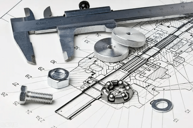
In mechanical design, technical or engineering drawing is an important skill for designers working on real products. These drawings help engineers share all the details and information needed to make a product or part correctly.
But what information is included in these drawings, and how do engineers understand them? In this article, we will explain everything about engineering drawings, including the different types of lines and views you’ll see in the field of engineering.
What is an engineering Drawing?
An engineering drawing is a type of technical drawing used to communicate all the necessary details about a product, such as its size, shape, surface finish, materials, dimensions, tolerances, and more. It provides all the information required to manufacture a product or part, including details for assembly or welding.
These drawings use standardized symbols and rules to ensure that they are clear and easy to understand, with minimal room for interpretation. By following these standards, engineers can read and understand the drawings accurately, no matter where they are or who they are.
Benefits of Engineering Drawing
An engineering drawing of a single part shows the structure, size, tolerances, and other important details of a part. There are many benefits to using engineering drawings, which can be summarized as follows:
Clear Communication
Engineering drawings help to standardize technical information. They show the size, shape, and tolerances, making it easy for everyone on the team to understand the technical details in the same way.
Visualization Of Design
Engineering drawings help engineers clearly understand the design. They can see how each part works and fits with others. This helps engineers focus on important areas during the manufacturing process.
Precise Dimensions
Engineering drawings provide exact dimensions. With views like section and detail views, important measurements are shown clearly, especially those critical for how parts function. For example, Geometric Dimensioning and Tolerancing (GD&T) can be included in the drawings to show exact requirements.
Quality Control
Engineering drawings are important for quality control. Manufacturing engineers use them as a reference to check the parts that are made. Only parts that match the specifications in the drawing are accepted. This ensures that parts are made correctly and reduces errors in production.
Types of engineering drawings
In the mechanical industry, engineering drawings are mainly used to show how parts and assemblies fit together. Two common types of drawings are assembly drawings and part drawings. Let’s take a closer look:
Assembly Drawing
Assembly drawings show how different parts connect and fit together to form a complete product. The components are made separately, and the assembly drawing helps engineers understand how each part will match and fit with others when put together.
Part Drawing
Part drawings focus on individual components. These drawings show exact measurements, materials, tolerances, surface finish requirements, and production notes. Part drawings are crucial for manufacturers and machinists, as they provide all the information needed to produce high-quality parts.
Main components of an engineering drawing
Technical drawings may have different components depending on the industry, the part and the purpose of the drawing. let is expore these compinents:
Types of lines
An engineering drawing uses various types of lines to represent different concepts and design details. Below, we explain the different types of lines used in these drawings:
Continuous Line
A continuous line is the most common type of line used in engineering drawings. It represents the physical boundaries of an object. These lines are used to outline the shape of objects. The thickness of the line can vary: thicker lines are used for the outer contour, while thinner lines are used for the inner contours.
Hidden Line
Hidden lines are drawn with dashed lines to represent edges or surfaces that are not visible in the current view. These lines show where surfaces meet but are hidden from sight. Hidden lines are usually left out of drawings unless they are necessary to make the design clearer.
Center Line
Center lines are used to represent parts with holes or symmetrical features. They indicate the center of a circular feature on a drawing and are characterized by a long-short-long alternating line pattern. Center lines can be used to show symmetry, paths of motion, and the centers of circles or axes of symmetrical parts.
Dimension and Extension Lines
Dimension and extension lines are thin lines used to show the sizes of features on a drawing. Dimension lines indicate the size or length of a feature and are marked with arrowheads at both ends to show the start and end of the measurement. Extension lines are used to show where a dimension begins and ends. They extend from the object and point to the features being measured.
Section Line
Section lines are used in section views to show the cut surfaces of an object. These lines are fine and dark, typically drawn at a 45° angle. The pattern of section lines can also indicate the type of material, such as steel, copper, or brass.
Cutting Plane Line
Cutting plane lines are heavy lines used in section drawings to show where the object has been “cut” to reveal the inside. These lines indicate the path of the cutting plane and help guide the viewer to understand the location of the cut.
Leader Line
Leader lines are thin lines used to point to a specific area of a drawing that needs further explanation or a note. These lines are usually drawn at a 45-degree angle to clearly link the note to the relevant part of the drawing.
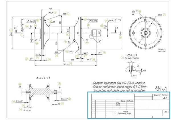
Title Blocks
In an engineering drawing, the title blocks are located in the lower right-hand corner. the title blocks show information such as:
- the company’s name
- The drawing number
- the name of the designer and reviewer
- Material
- Mass
- drawing scale
- surface finish standard
- General tolerances
- projection angle
- Scale used in the drawing
- Revision numbers
- Status of the drawing (Preliminary, Approved, etc.)
- unit measurements
Drawing Views
Engineering drawings often use different types of views to help explain a design more clearly. Here are the main types of views commonly used:
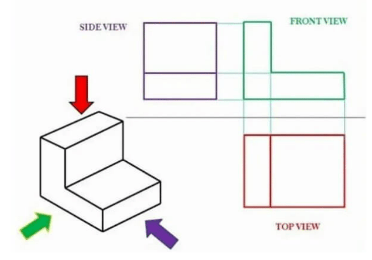
Basic View
A basic view is created by placing the part in a projection system with six basic projectors. The part is then projected onto these six projectors to produce six basic views. However, in most cases, only three views are used in an engineering drawing: the front view, side view, and top view. These three views provide enough information to understand the design.
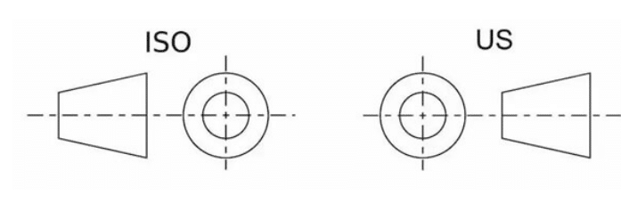
Regionally, the layout of views in engineering drawings can differ. For example, the drawing layouts used in the US and ISO are quite different. The layout on the left is known as first-angle projection, while the layout on the right is called third-angle projection. These two projection methods are in direct opposition to each other, with the way views are positioned and arranged varying between the two systems.
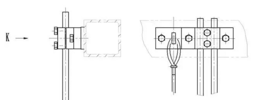
Directional view
A direction view indicates a view according to the projection direction on the main view or another view, it is a view that is not configured according to the projection of basic views. If a view cannot be configured according to the projection, it can be drawn according to the direction view.
Sectional View
The section view is mainly used to express the internal structure of the parts, it is supposed to use a section plane or surface to cut the parts, the part between the observer and the section plane is removed, and the rest of the part is projected on the plane.
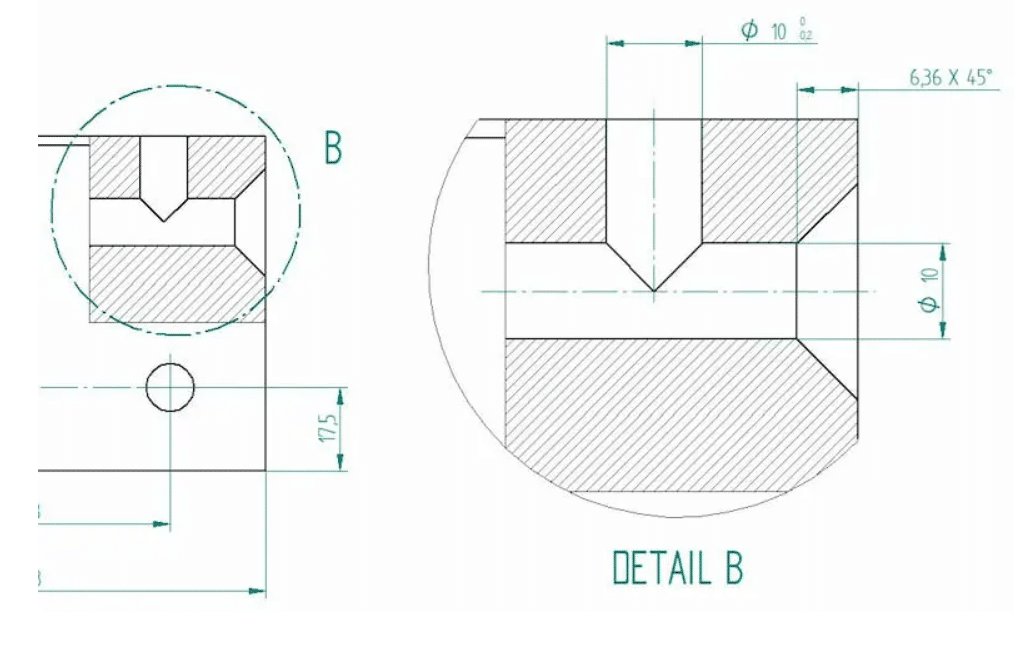
Detail View
The detailed view focuses on a specific area or feature of the object, providing an enlarged and magnified view for accurate representation and dimensioning.
Auxiliary View
The auxiliary view is used to display inclined or non-orthogonal surfaces that cannot be accurately represented in other views.
Dimensions And Tolerances
Due to machining stability, the actual dimensions can’t be the same as the dimensions in the 3D data of a product. this is where tolerance comes from, The actual size after manufacturing should be within the specified range of the maximum and minimum limit dimensions. below are the related definitions of dimension and tolerance.
- Basic size: The dimension given by the designer.
- Actual size: The dimension obtained through measurement.
- Limit dimensions: The two extreme permissible values of a dimension variation, which are the maximum and minimum limit dimensions, are determined based on the basic size.
- Zero line: A baseline in the tolerance band diagram (limit and fit explanatory diagram) that determines deviation, i.e., the zero deviation line. The basic size is usually represented by the zero line.
- Dimensional Tolerance: Abbreviated as tolerance, it is the difference between the maximum and minimum limit dimensions, and it represents the allowable amount of variation in size. Dimensional tolerance is always a positive value.
- Standard Tolerance: In the system of limits and fits, any prescribed tolerance. The national standard stipulates that for a certain basic size, there are 20 tolerance grades of standard tolerances.
- Tolerance Zone: In the tolerance band diagram, the area is defined by two straight lines representing the upper and lower deviations.
- Geometric tolerances: The allowable variations in the shape or position of parts that can affect the function of mechanical products. These deviations need to be specified during the design process and shown on the drawings using standardized GD&T symbols.
How to Create an engineering drawing?
In the past, engineering drawings were created manually using tools like drawing boards, rulers, and round gauges. This process could take days or even weeks to complete a single drawing for a component, making it slow and prone to mistakes.
Today, engineering drawings are created using CAD (Computer-Aided Design) software, which allows engineers to create drawings directly on a computer. There are various types of CAD software available, some of which are specific to certain industries. With CAD, engineers can either create a drawing from scratch or design a 3D model and then convert it into a 2D drawing.
Given the many advantages of CAD, it is now the standard tool every engineer should use. While you can create drawings from scratch with CAD, the easier method is to first design a 3D model. From this model, CAD programs can quickly generate the necessary views with just a few clicks. You only need to add the dimensions. Additionally, having 3D models makes it much easier to update and revise drawings as needed.
Conclusion
Engineering drawings are one of the best ways to communicate all the technical information. At KUSLA Prototype, our team of skilled engineers and machinists is experienced in analyzing every aspect of engineering drawings. We provide prompt Design for Manufacturability (DFM) feedback to ensure the highest quality machined components. Take the next step by uploading your CAD files and receiving a quote today!
FAQ
How do you read engineering drawings easily?
Engineering drawings are composed of several key parts. By reading them in the following steps, you can quickly understand the drawing:
1.Get critical product information from the information block, which contains details about the object depicted in the drawing and the people involved in creating it.
2.Understand the symbols and abbreviations, including specifications and dimensions.
3.Read the lines and views to understand how they are reflected in the 3D data.
Why not just use a 3D model?
While 3D models provide a lot of information, some details cannot be fully captured in them. Engineering drawings are needed to provide additional information, such as geometry, tolerances, materials, surface finishes, and more.
What are the common mistakes in engineering drawings?
Common mistakes in engineering drawings include inconsistency in dimension data, over-dimensioning, missing critical specifications, incorrect tolerances, and more. These mistakes can make it difficult for manufacturers to produce parts correctly.