

Online CNC Machining Service
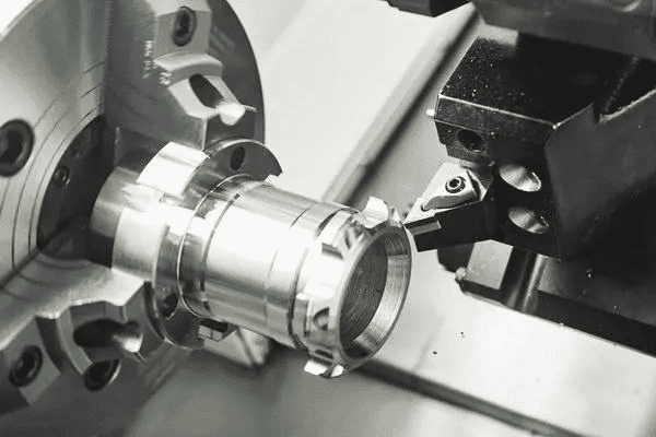
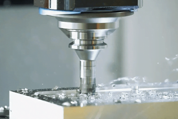
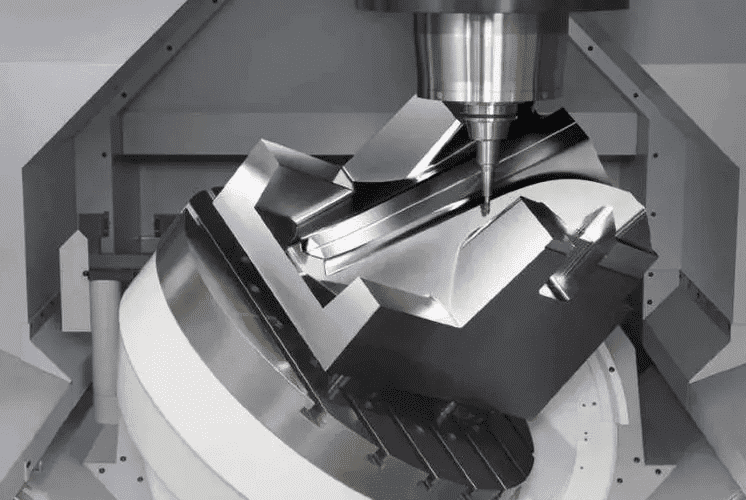
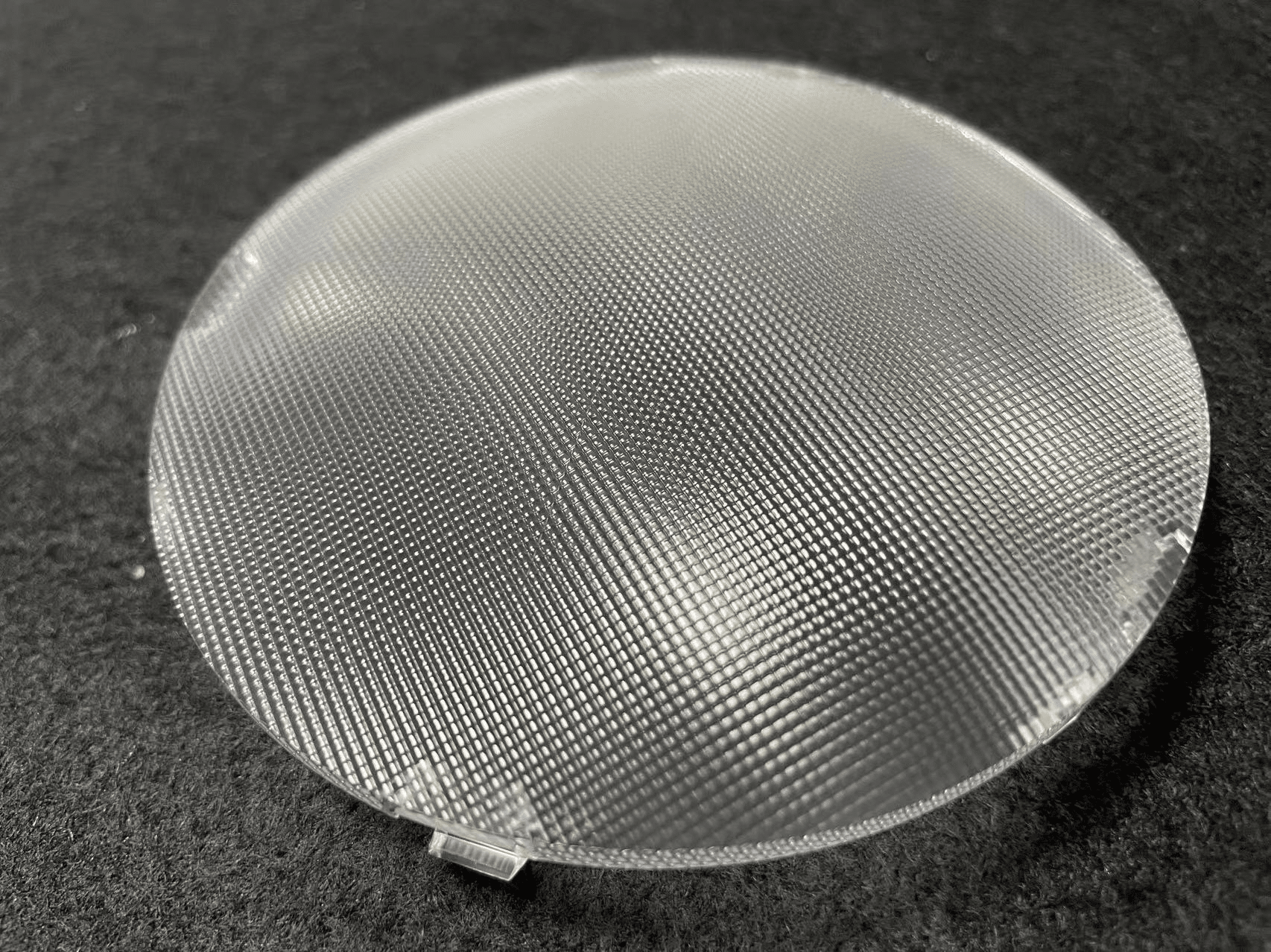
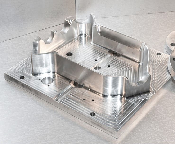
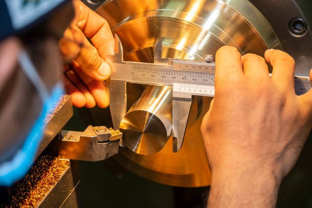
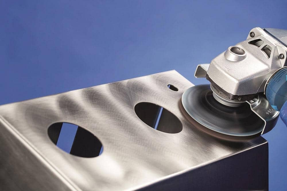
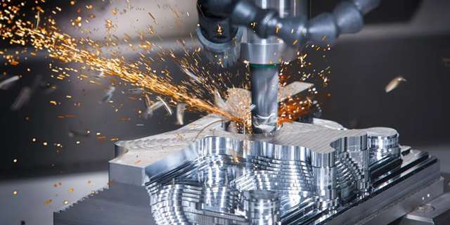
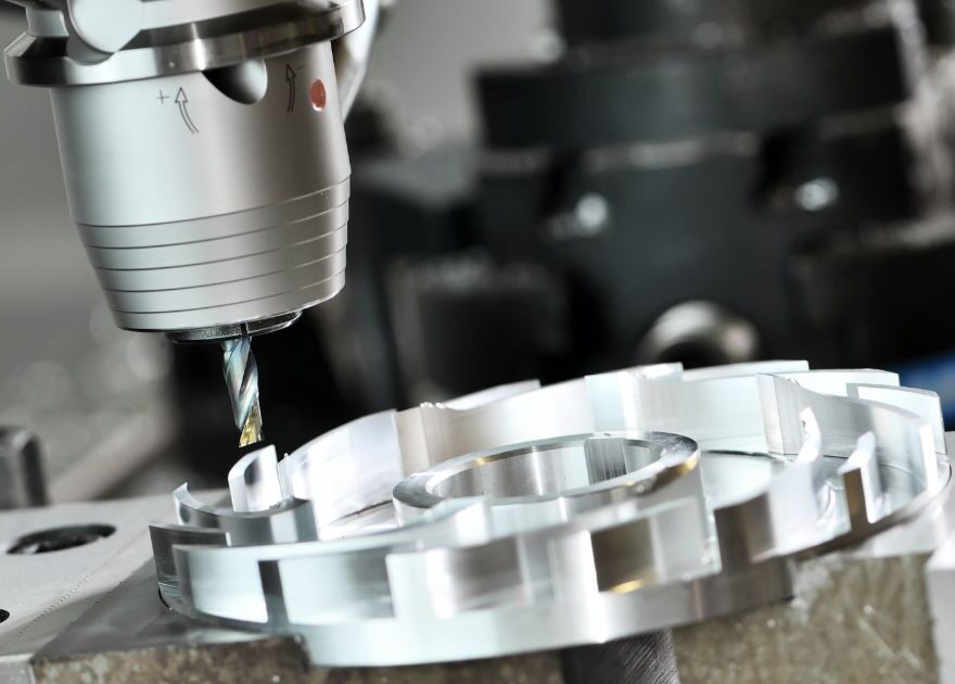
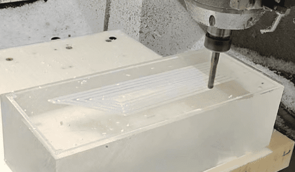
Kusla in China offers comprehensive CNC machining services, including CNC turning and CNC milling, along with surface finishing capabilities to deliver high-quality prototypes and low-volume CNC machined parts.
15+ YEARS OF EXPERIENCE
ISO9001: 2015 CERTIFIED
One-stop Machining and Finishing


