CNC stands for Computer Numerical Control, which means using a computer to control machining tools automatically. But this doesn’t happen on its own—it requires a specific set of instructions written in code. So, what are G-code and M-code? And how do they work? This article will explain both.
What Are G-Code And M-Code?
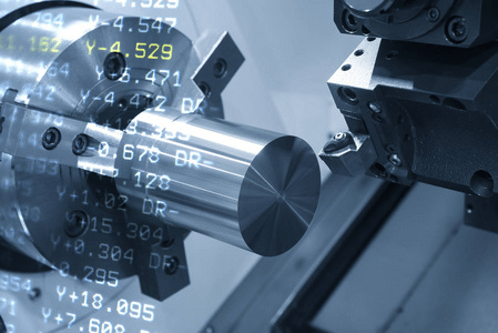
G-code and M-code are programming languages used to control CNC machines and guide the movement of cutting tools to shape a part. These codes tell the machine exactly what to do, such as where to move, how fast, and when to change direction. While creating these programs can be complex because they can vary between different machines, the basics of G-code and M-code are fairly simple and follow industry standards.
Today, machinists enter instructions into software, which automatically generates the necessary G-codes and M-codes for the CNC machine. Thanks to advanced CAD and CAM software, this process is now much easier and faster, improving both the precision and complexity of manufacturing.
What is G-code in CNC Programming?
In simple terms, G-code is a programming language used to control a CNC machine. Even though CNC machining can be complex, G-code is written in a clear and easy-to-understand way.
A “G” followed by a number is a command that tells the machine to change the shape or position of a part. For example, “G00” tells the machine to move quickly. It moves the tool to the part’s location as fast as possible, usually to go from one point to another.
How does G-Code work?
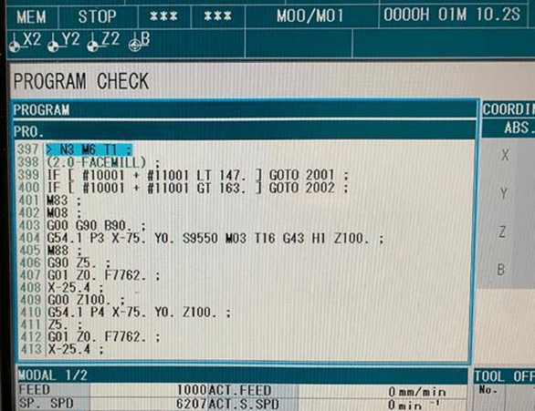
We take some main functions of G-code to explain as below:
Rapid Positioning
Format: G00 X(U)Z(W)
- The instruction makes the tool move quickly to the specified position; The workpiece shall not be processed during movement.
- when one axis completes the programming value, it stops, while the other axes continue to move.
- G00 can be written as G0.
Example: G00 X75 Z200 G01 U-25 W-100: First, along with X and Z axis move simultaneously at a rapid speed to point A by 25 units, then along Z continues to move rapidly to point B by 75 units.
Linear Interpolation
Format: G01 X(U)_Z(W)F(mm/min)
- This command moves the tool to the specified position in a linear interpolation manner. The feed speed is controlled with F command. All coordinates can be run in tandem.
- G01 can also be written as G1.
Example: G01 X40 Z20 F150: Two-axis simultaneous movement from point A to point B.
Arc Interpolation Mia
Format: G02 X(u)_Z(w)I_K_F
- When X and Z are at G90, the end coordinate of the arc is the absolute coordinate value compared to the programming zero. At G91, the end of the arc is the increment relative to the beginning of the arc. I and K are the incremental coordinates of the center of the arc compared to the starting point.
- When the G02 instruction is programmed, it can be directly programmed through the quadrant circle, the whole circle, etc.
- G02 can also be written as G2.
Example: G02 X60 Z50 I40 K0 F120: Programming a quadrant arc with specified parameters.
Dwell
Format: G04_F_ or G04_K_
During machining, motion is paused, and after the specified time, machining continues. The pause time is specified by the data following F. The unit is in seconds, ranging from 0.01 seconds to 300 seconds.
Intermediate Point Arc Interpolation
Format: G05 X(u) Z(w) IX IZ F
X and Z are the endpoint coordinates, while IX and IZ are the coordinates of the intermediate point. Similar to G02/G03 with additional parameters.
Example: G05 X60 Z50 IX50 IZ60 F120
Acceleration/Deceleration
Format: G08
These commands occupy a line by themselves in the program. When the program reaches this section, the feed rate will increase by 10%. To increase it by 20%, you would need to write two separate lines.
Radius Programming
Format: G22
When placed on a line by itself in the program, the system will operate in radius mode, and the values following in the program will also be interpreted as radius values.
Diameter Dimension Programming
Format: G23
When placed on a line by itself in the program, the system will operate in diameter mode, and the values following in the program will also be interpreted as diameter values.
Jump Machining
Format: G25 LXXX
When the program reaches this segment, it transfers to the specified program segment (XXX represents the program segment number).
Loop Machining
Format: G26 LXXX QXX
When the program reaches this segment, it starts the program segment specified by LXXX as a loop, and the number of repetitions is determined by the value following QXX.
Common G-Codes
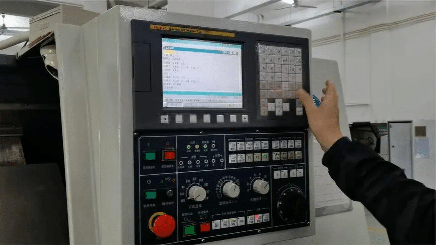
G Code command could be used in both CNC milling and CNC lathe machines to control the movements of CNC milling tools and CNC lathe cutting tools.
Tool Movements
- G00 Rapid linear movement
- G01 Linear feed movement
- G02 Clockwise arc
- G03 Counterclockwise arc
- G05 Arc
- G06 Arc, tangent
- G07 Linear, parallel axis
- G10 Rapid polar coordinate linear movement
- G11 Polar coordinate linear feed
- G12 Clockwise polar coordinate arc
- G13 Counterclockwise polar coordinate arc
- G15 Polar coordinate arc
- G16 Polar coordinate arc, tangent transition
Defining Machining Planes
- G17 Spindle Z-plane XY
- G18 Spindle Y-plane ZX
- G19 Spindle X-plane YZ
Chamfering/Rounding/Approaching
- G24 Chamfer of length R, chamfer length R
- G25 Radius R rounding, radius R
- G26 Tangent approach to contour with radius R
- G27 Tangent exit contour, radius R
Defining Workpiece For Graphic Display
- G30 Workpiece definition: minimum point
- G31 Workpiece definition: maximum point
Tool Radius Compensation
- G40 Tool center path, no tool radius compensation
- G41 Left radius compensation path
- G42 Right radius compensation path
- G43 Radius compensation: expanding path
- G44 Radius compensation: retracting path
Coordinate Transformation
- G28 Mirroring
- G53 Origin shift using the origin table
- G54 Origin shift
- G55 Origin plane
- G73 Rotation
- G72 Scaling factor
- G80 Machining plane
- G247 Origin setting
Dimension Units
- G70 Dimension units in inches (program starting point)
- G71 Dimension units in millimeters (program starting point)
Dimensions
- G90 Absolute dimensions
- G91 Incremental dimensions
Tool Definition
G99 Tool definition, tool number T, length L, and radius R
Other G Codes
- G04 Dwell time
- G37 Contour
- G38 Stop program execution
- G36 Spindle orientation
- G39 Program call
- G55 Origin plane
- G62 Tolerance
- G79 Repeat call
- G29 Load current position (e.g., polar coordinates with the center as the origin)
- G51 Tool change preparation (with a central tool magazine)
- G98 Set mark
What is M-code in CNC Programming?
M-code is a programming language in CNC machines that controls extra functions, not related to the cutting or shaping of a part. It manages tasks like starting, stopping, and other actions that support the main work. Think of M-codes as commands for the machine’s helper functions, such as turning the spindle on or off, switching coolant flow, or stopping the machine. These functions might vary depending on the machine
Common M-Codes
- M00: Program execution pause/spindle stop/coolant stop
- M01: Optional program stop
- M02: Program stop/spindle stop/coolant stop/as required
- M03: Spindle clockwise rotation
- M04: Spindle counterclockwise rotation
- M05: Spindle stop
- M06: Tool change/program stop (depends on machine parameters)/spindle stop
- M08: Coolant on
- M09: Coolant off
- M13: Spindle clockwise rotation/coolant on
- M14: Spindle counterclockwise rotation/coolant on
- M30: Same as M02
- M89: Auxiliary function or repeat call available
- M99: Program segment repeat call
- M91: Positioning program segment, coordinates relative to the machine tool origin
- M92: Positioning program segment, coordinates defined relative to the machine tool manufacturer
- M94: Reduce rotation axis display to within 360°
- M97: Processing small contour steps
- M98: Complete processing of an open contour
- M109: Constant contour processing speed at tool edge (increase and decrease feed rate)
- M110: Constant contour processing speed at tool edge (only decrease feed rate)
- M111: Reset M109/M110
- M116: Rotary axis feed rate (mm/min)
- M117: Reset M116
- M118: Manual wheel overlay positioning during program execution
- M120: Pre-calculate radius compensation contour (pre-read)
- M126: Rotary axis short-path motion
- M127: Reset M126
- M128: Maintain the tooltip position when positioning with a tilted axis (TCPM)
- M129: Reset M128
- M130: In the positioning program segment: points are relative to the untilted coordinate system
- M140: Retract from the contour along the tool axis direction
- M141: Cancel probe monitoring function
- M143: Delete basic rotation
- M148: Automatically retract tool from contour at NC stop
- M149: Reset M148
What are the Differences Between G-Code and M-Code
G-code and M-code serve different but essential functions in controlling CNC machines.
G-code is used for controlling the movement and cutting actions of the CNC machine. It includes commands that tell the tool where to go and how to cut, handling actions like moving to specific positions, adjusting speed, and creating different shapes. Think of G-code as the set of instructions that guides the machine’s cutting paths and tool positions.
M-code, on the other hand, manages auxiliary or non-cutting tasks that support the main operations. These commands handle machine functions such as starting or stopping the spindle, changing tools, or turning coolant on or off. In short, M-code tells the machine when to carry out actions that don’t involve direct cutting. Here we make a summary for better understanding G code and M code.
- G-codes:
- Control the movement and cutting paths.
- Describe positions, speeds, and shapes.
- Focus on the geometry and design of the part.
- M-codes:
- Manage non-cutting functions, like spindle start/stop and coolant on/off.
- Control machine-specific tasks and support operations.
Conclusion
Today, programming methods like CAD/CAM software, that don’t require knowing G and M codes. However, it’s still useful for a programmer to understand them because, sometimes, special situations need manual programming. The good news is that G and M codes are almost universal, meaning once you learn them, you can program nearly any CNC machine. The basic commands stay the same, with only minor differences that are easy to pick up.
If you’re looking for a skilled CNC programmer for your product, KUSLA has the tools, materials, and G&M code expertise to deliver high-quality machined parts. For any CNC machined prototypes or parts, check out our prototype CNC machining service!


